X3D Rendering of NURBS surfaces: Example models and browser support
August 31, 2011
X3D models demonstrating NURBS surface geometry nodes
These X3D files (with XML encoding) are examples of use of the NurbsPatchSurface node and NurbsTrimmedSurface node of the X3D Nurbs Component.
Each scene includes a triad of line segments showing position of global coordinate system origin and x axis (red), y axis (green), and z axis (blue). Surfaces are semi-transparent.
X3D browsers support NURBS surface rendering
The following X3D browsers support all or part of the NURBS Component. All four browsers render the nurbs_patch example:
Summary
It was discovered, and the screenshots shown below illustrate, that each browser renders the geometric position and shape of the patch as expected. There are differences among them with other features of the NURBS rendering. The differences originate in a disagreement among browsers as to how the coordinate system on the surface of the patch is defined. Octaga Player, view3dscene, and BS Contact define the (u,v) coordinate system in accordance with the NURBS Component specification. The Instant Player browser transposes the (u,v) coordinate axes compared with the specification.
NURBS surface parameter definition
The geometric parameters defined as fields of the abstract X3DNurbsSurfaceGeometryNode serve both to define a bounded 2-dimensional patch in 3-d space and also to specify a 2-parameter coordinate system on this patch. The coordinate system defined on the patch effects rendering in three ways:
- When a texture is applied to the patch the texture coordinates are derived from the defined coordinate system.
- When the field solid='true' of a NURBS geometry node the side of the patch which will be visible is determined by the geometric orientation of the coordinate system defined on the patch.
- When trimming curves are applied to the patch in the NurbsTrimmedSurface node, these curves are defined in the coordinate system defined on the patch.
The surface patch is cylindrical around the z-axis, the quarter of the cylindrical segment in the x > 0 , y > 0 quadrant comprises the patch. Because of the discordance among browsers to be discussed, for this section these coordinate parameters will be referred to as the row-parameter and the column-parameter.
The geometry of the patch is specified by an array of control points with NR rows and NC columns. Each element Pi,j of this array is a SFVec3f value (3 components of the control point in rational space). The example models use a (5,2) array of control points:
| P0,0 |
P0,1 |
| P1,0 |
P1,1 |
| P2,0 |
P2,1 |
| P3,0 |
P3,1 |
| P4,0 |
P4,1 |
There is a corresponding (5,2) array of weight values (each element a SFFloat scalar.)
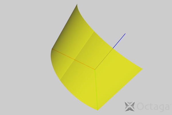
The geometric positions of the control points is illustrated in Figure 1. Increasing the row-parameter (first index) corresponds to wrapping azimuthally about the axis in a counter-clockwise direction as seen from the +z direction. Increasing the column-parameter (second index) index value corresponds to increasing in the axial (z) direction.
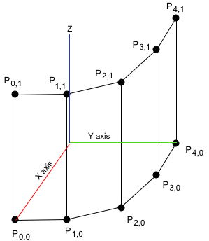
Figure 1: Control points in 3D space.
The spline definition are completed by defining for each parameter the order of the spline and a knot vector.
For the row-parameter the order DR is an integer (DR = 2 corresponds to linear splines, DR = 4 is cubic splines.) The knot vector for the row-parameter is an ordered (ascending) list of KR parameter values. The example models have DR=3 and KR=8.
For the column-parameter the order DC. The knot vector for the column-parameter is a list of KC=4 values.
The definition of the spline functions requires that the spline parameters and dimensions of the control points array satisfy:
- KR = NR + DR
- KC = NC + DC
These parameters are entered into the fields of the NurbsPatchSurface node according to Section 27.3.2 of the NURBS Component specification. The weights and control point arrays are flattened into lists by traversing the arrays in column major order.
-
controlPoint ← P0,0, P1,0, P2,0, ...P4,0,P0,1,...,P4,1 ; each P a SFVec3f value.
-
weight ← w0,0, w1,0, w2,0, ...w4,0,w0,1,...,w4,1 ; each w a SFFloat value.
- uKnot ← row-parameter knot vector, of length KR=8
- uDimension ← NR=5
- uOrder ← DR=3
- vKnot ← column-parameter knot vector, of length KC=4
- vDimension ← NC=2
- vOrder ← DC=2
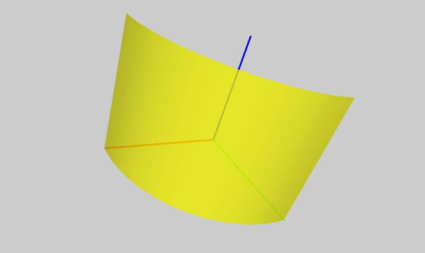
These values are used in the model nurbs_patch. For this model the solid = 'false' field of the NurbsPatchSurface node ; both sides of the patch are visible. All browsers listed above render this model the same way; the Instant Player rendering is shown in Figure 2.
u-v coordinate definition and texture coordinates
The explanation above has used the labels row-parameter and column-parameter for coordinates on the patch, while the Specification uses the labels u and v. The specification and in particular the naming of the uOrder, vOrder, etc. fields suggests the identification:
u ← row-parameter [azimuthal direction in models]
v ← column-parameter [axial direction in models]
Table 1: parameter assignment as implemented by Octaga Player, BS Contact, and view3dscene browsers
With this assignment the u coordinate on the patch inceases counterclockwise around the z - axis (as seen from the +z direction) and the v coordinate increases parallel to the z axis on the patch surface.
Whether or not browsers implementing the NURBS component honor this assignment can be checked by rendering the patch with a texture image. I interpret Section 27.4.13 to specify that in the absence of a NurbsTextureCoordinate node the texture coordinates (s,t) are derived directly from the patch surface coordinates (u,v) : s=u ; t = v.
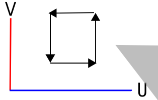
Figure 3: Image used as texture bitmap to place on NURBS patch. The oriented loop is used to establish the outside and inside directions from the surface when the solid field is true. The gray triangle shows the notch removed in the NurnbsTrimmedSurface node examples.
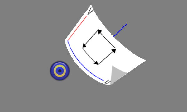
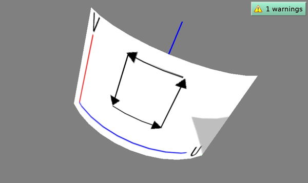
Figure 3 shows the image to be used which displays the (u,v) coordinate system. Figure 4 shows a the Octaga Player rendering of the nurbs_patch_texture model; confirming that the (u,v) coordinate system is defined in Table 1. Figure 5 shows the nurbs_patch_texture model as rendered by the Instant Player browser. It appears that this browser has made a different mapping of the defined patch coordinates:
v ← row-parameter [azimuthal direction in models]
u ← column-parameter [axial direction in models]
Table 2: parameter assignment as implemented by Instant Player browser
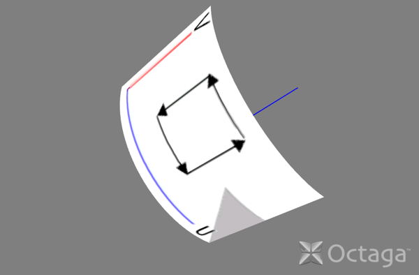
Figure 4: Rendering of nurbs_patch_texture model (NurbsPatchSurface and applied image texture) by Octaga Player browser. Similar rendering is done by
BS Contact and
view3dscene.
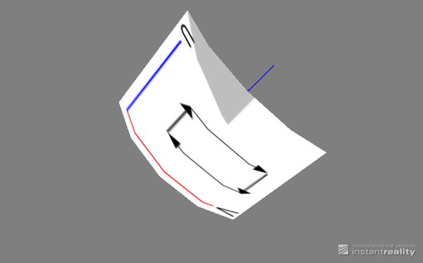
Figure 5: Rendering of nurbs_patch_texture model (NurbsPatchSurface and applied image texture) by Instant Player browser.
solid field and visibility
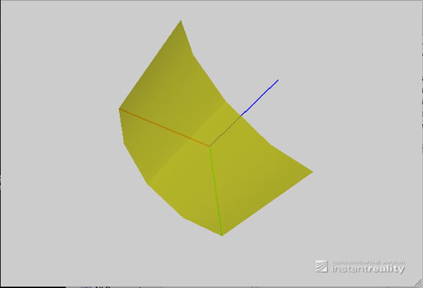
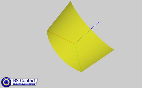
The assignment of the (u,v) coordinate system to the patch determines the effect of the solid field. When solid = 'true' for a surface geometry node one side, the 'outside', is visible. The surface is transparent or invisible when the viewpoint of the browser is directed toward the opposite 'inside' of the surface (See Specification 11.2.3). The definition of the inside and outside of a NurbsPatch is defined in the 2011 Amendment to the NURBS Component. A loop such as described in this definition is illustrated in Figure 3. Since this loop is traversed counter-clockwise in Figure 4 as seen from the displayed viewpoint, it would be expected that the convex side of the surface will be visible when the solid = 'true'; and Figure 6 confirms this. Likewise, under the assignment defined by the Instant Player browser (Figure 5), the directed loop would appear counter-clockwise when looking from the axis toward the patch; so the concave side of the surface should be visible. Figure 7 confirms that this is the case.
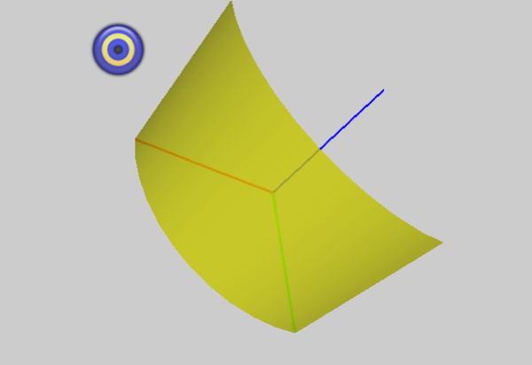
Figure 6: Rendering of NurbsPatchSurface with solid='true' by BS Contact browser. Only outer surface of cylinder is visible. Octaga Player and view3dscene render this model the same way.
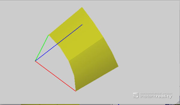
Figure 7: Rendering of NurbsPatchSurface with solid='true' by Instant Player browser. Only inner surface of cylinder is visible.
Trimming NURBS patches
A final way to check the assignment of the (u,v) coordinates on a NURBS patch is to trim the patch with an outer boundary curve in the TrimmedNurbsSurface node. Trimming requires that a boundary curve be definined in the (u,v) coordinate system. Figure 8 shows such a trimming curve defined to notch out a part of the patch corresponding to the gray section of the image of Figure 3. Only the Instant Player and Octaga browsers render the TrimmedNurbsSurface node in the nurbs_trimmed.x3d model. Figures 9 and 10 demonstrate that each of these browsers trims the surface in a way consistent with the way they hande texture coordinates and the solid field.
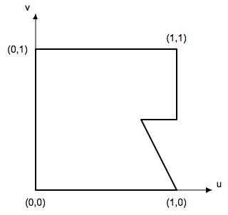
Figure 8: trimming curve
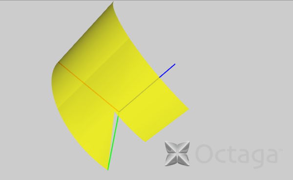
Figure 9: Rendering of trimmed_nurbs model by Octaga Player.
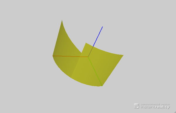
Figure 10: Rendering of trimmed_nurbs model by Instant Player.
Note on Octaga status: The Octaga website at http://www.octaga.com has been offline since early 2011. As of August 2011 the status of the company (Octaga AS) and its product line is unknown.
Added Jan 21, 2012
For this NURBS example there is a simpler way of visualizing the u,v coordinate system intended by the X3D specification. The control point P0,0 determines the origin of the u,v coordinate axes, or at least the point in real (xyz) space for which u and v take on their minimum values. Regardless of how the array of control points is flattened to a list the point P0,0 should be the first element of that list. From the listing of the file nurbs_patch this list is the attribute point of the X3D node NurbsPatchSurface/Coordinate:
<Coordinate containerField="controlPoint"
point=" 1.0000e+00 0.0000e+00 0.0000e+00,
9.2388e-01 3.8268e-01 0.0000e+00,
7.0711e-01 7.0711e-01 0.0000e+00,
3.8268e-01 9.2388e-01 0.0000e+00,
0.0000e+00 1.0000e+00 0.0000e+00,
1.0000e+00 0.0000e+00 1.0000e+00,
9.2388e-01 3.8268e-01 9.2388e-01,
7.0711e-01 7.0711e-01 1.0000e+00,
3.8268e-01 9.2388e-01 9.2388e-01,
0.0000e+00 1.0000e+00 1.0000e+00"/>
and the point P0,0 is located at (x,y,z) = (1,0,0) , which in the figures above is the endpoint of the x-axis (red) line segment.
The order of the v-parameter spline functions is set to 2 as the value of the vOrder attribute in the NurbsPatchSurface node
<NurbsPatchSurface
vOrder="2"
vKnot="0.0 0.0 1.0 1.0"
vDimension="2"
uOrder="3"
uDimension="5"
uKnot="0.0 0.0 0.0 0.5 0.5 1.0 1.0 1.0"
...
</NurbsPatchSurface>
This corresponds to polynomial functions of degree 1, which are linear in the parameter v. As a result, the curves on the surface corresponding to constant u, varying v must be straight lines in (xyz) space. Conversely, the attribute uOrder has value 3; the spline functions have a degree=2 (quadratic) dependence on u, and may be curved in (xyz) space. We see that the v-axis of the uv coordinate system must be axial, that is parallel to the cylinder axis; which is the z-axis (blue) in the figures above.
These points, the location of the uv system origin, and the orientation of the v axis, together show that Figure 4 above illustrates how the X3D specification intends that the uv coordinate system be placed on the NURBS surface for this example.
Added March 31, 2012
Edited 11 June, 2012
All example files specify the Immersive profile, at version 3.2 of the X3D standard. Each example file additionally specifies use of the NURBS components (which is not otherwise included in the Immersive profile) through a COMPONENT statement in the header section. The files which demonstrate the NurbsPatchSurface specify conformance to Level 1 of the NURBS component, while the file which demonstrates the NursbTrimmedSurface node specifies and requires Level 4 conformance.